


Description:
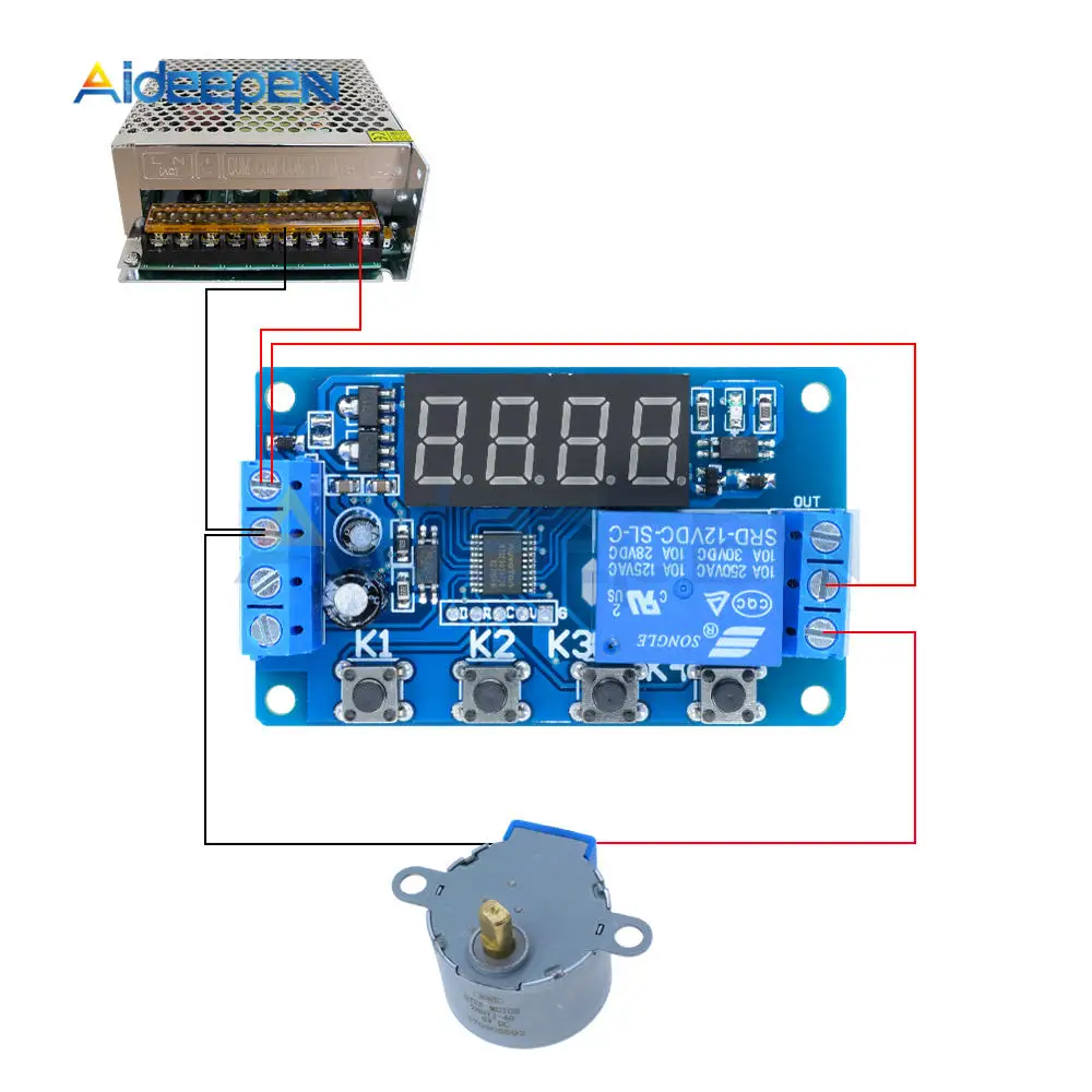
Product model: YYC-2S 24 common functions, to meet more application needs; can control solenoid valves, pumps, motors, lights, etc.
Input voltage: DC 5/12/24V optional
Output power: can control DC or AC load within 10A
Time range: 0.01 seconds to 999 minutes adjustable at any time
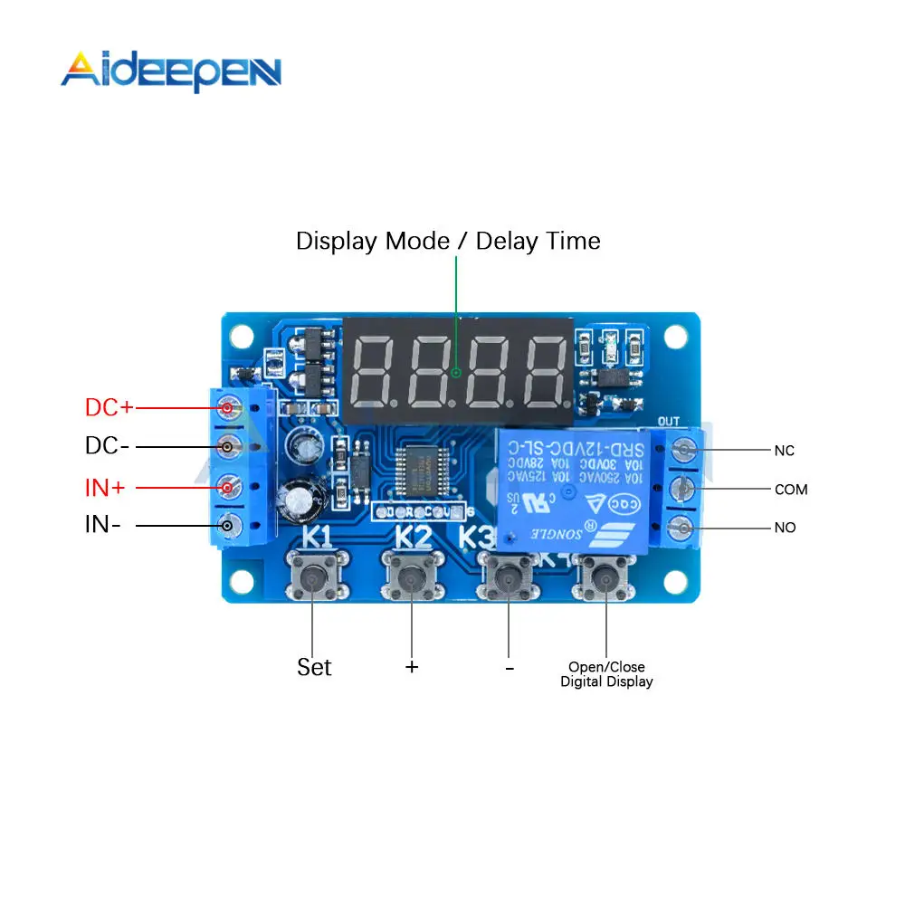
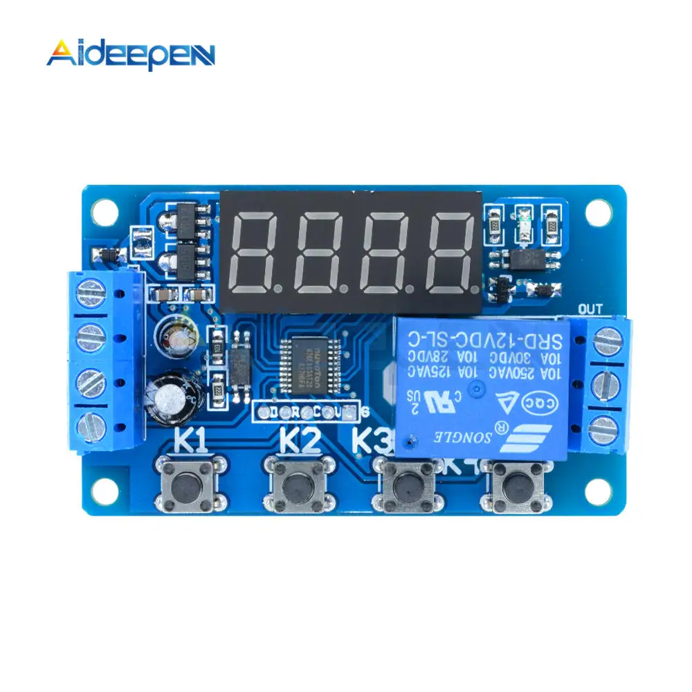
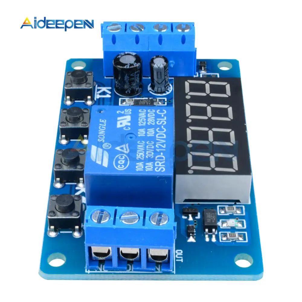
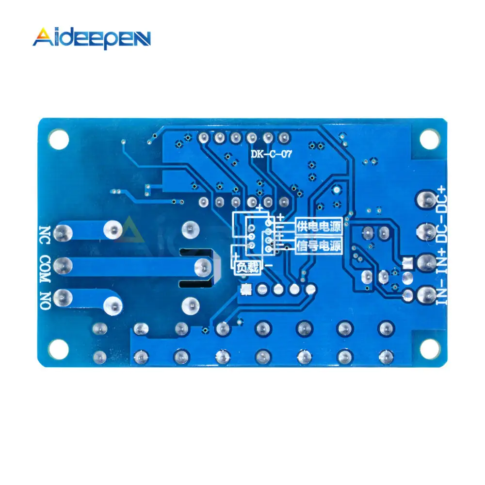
Description of the wiring port:
1, DC+: input DC power supply positive
2, DC-: input DC power supply negative
3. IN+: positive input terminal
4, IN-: signal input terminal
5, NO: relay normally open interface, the relay is suspended before the suction, after the suction and short circuit with COM
6, COM: relay common interface
7. NC: The relay normally closes the interface, and the relay is shorted to COM before the suction is closed.
Function list:
P-11: Jog P-12: Self-locking P-13: Give signal, the relay will stop automatically for A seconds; the trigger will be invalid during the delay.
P-14: Give signal, relay will stop automatically for A seconds; trigger re-time during delay
P-15: Give signal, relay is automatically stopped for A seconds; trigger timing is triggered during delay
P-16: Give signal, relay will stop automatically for A seconds; trigger reset during delay
P-17: Give signal, relay is closed, input signal is disconnected, output is off after A seconds
P-18: After power-on, the relay will immediately pull in, after a delay of A seconds, the power will be turned off;
P-21: Disconnect the signal relay, after a delay of A seconds, the relay pulls in
P-22: Give signal, after more than A seconds, the relay pulls in, the signal disappears, the relay stops.
P-23: After the signal disappears for more than A seconds, the relay is closed, there is a signal, and the relay stops.
P-24: There is a signal. After more than A seconds, the relay is closed. When the signal disappears for more than A seconds, the relay stops.
P-25: There is a signal after more than A seconds, the relay is closed, and after a signal exceeds A seconds, the relay stops.
P-26: There is a signal. The relay stops after A seconds of suction, and the signal disappears. The relay stops again after A seconds.
P-27: The pulse signal is detected and the relay is closed; if there is no pulse signal, the relay delays for A seconds;
P-28: After power-on, after a delay of A seconds, the relay pulls in until the power is turned off.
P-31: After power-on, the relay pulls in for A seconds, disconnects B seconds, infinite loop; power-off stops P-32: signal, start P-31
P-33: Give a signal, start P-31 infinite loop; give another signal to terminate the loop
P-34: After power-on, after a delay of A seconds, the relay pulls in and closes after B seconds.
P-35: There is a signal. After a delay of A seconds, the relay pulls in and closes after B seconds.
P-36: There is a signal. After more than A seconds, the relay pulls in and closes after B seconds.
P-37: There is a signal, the relay will stop automatically for A seconds, and then stop for 24 seconds. The signal trigger is invalid during A+B time.
P-38: There is a signal, the relay will stop automatically for A seconds, stop and re-time for B seconds, and then automatically close for A seconds.
P-41: There is no signal; the signal disappears; the relay works after the delay of A time.
P-42: The signal disappears, after a delay of A time, the relay works; the end of work B time
P-43: The signal disappears. After the A time, the relay works; the working B time ends.
P-44: After power-on, the relay works for A time, and stops B time; the cycle stops automatically for C times.
P-45: The power is not activated, after the signal is given; the relay works for A time, the B time is stopped; the cycle C stops automatically; the signal is given again, once again
P-46: After the signal is sent for more than A times, the relay is closed; the suction is kept; the power is stopped.
P-47: After the signal is sent for more than A times, the relay is closed for B seconds.
P-48: In C seconds, after the signal is continuously sent for more than A times, the relay is closed for B seconds.
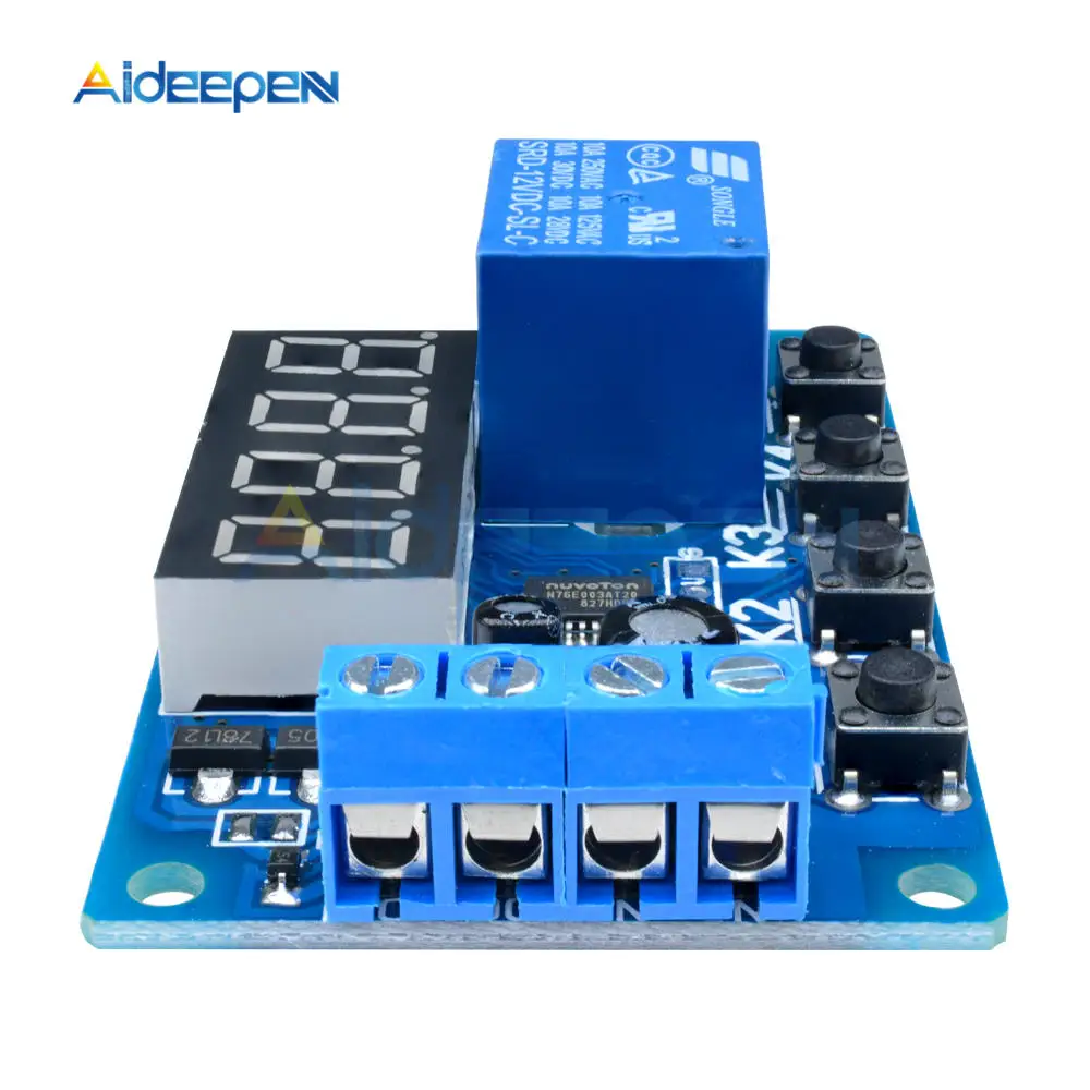
Button setting instructions:
The power-on display “————” means to enter the standby state;
Press K1 for the first time (more than 1 second is required to prevent false triggering)
Screen display: P -11: K2 adjusts the main mode, K3 and K4 adjustment functions
Press the second time K1, the screen displays: A001: K2 and K3 adjust the first time A, K4 adjust the decimal point (time unit)
Pressing the third K1, the screen displays: B001: K2 and K3 adjust the second time B, K4 adjusts the decimal point (time unit)
Pressing the fourth K1, “————” means entering the standby state;
Press K4 in standby mode to permanently turn off/on the display and switch the low power mode.
X.XX decimal point in hundred, timing range: 0.01 seconds to 9.99 seconds
XX.X decimal point in ten, timing range: 0.1 seconds to 99.9 seconds
XXX has no decimal point, timing range: 1 second ~ 999 seconds
XXX. The decimal point is in one place, the time range is from 1 minute to 999 minutes.
Package included:
1PCS x DC 5V 12V 24V LED Display Digital Delay Relay Delay Timer Control Switch Module 4 Button 4 Digit Digital Tube Red 10A