


Description:
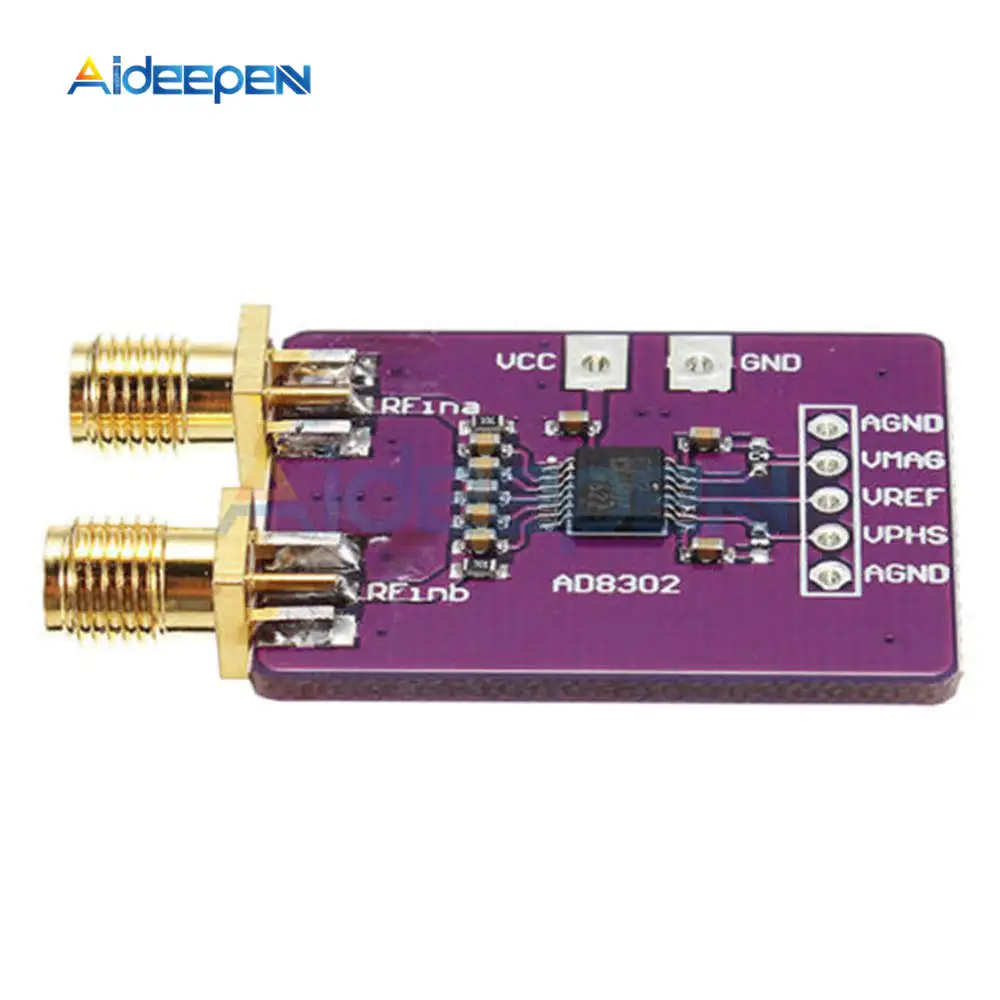
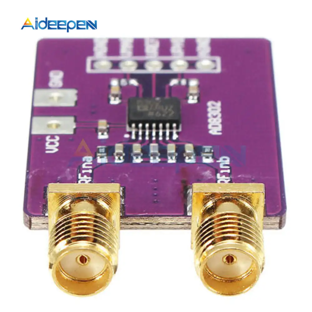
8302 is a phase detection circuit module, using AD8302 chip, AD8302 is used for RF / IF amplitude and phase measurement of monolithic integrated circuits, mainly by the precision matching of two broadband logarithmic detector, a phase detector, the output An amplifier group, a bias unit, and an output reference voltage buffer. It can simultaneously measure the amplitude ratio and phase difference between the two input signals from the low frequency to the 2.7 GHz frequency range and can be applied to RF / IF power amplifiers Linear ratio measurement, RF power precision control, VSWR measurement and remote system monitoring and diagnosis.
Features:
(1) The amplitude ratio (gain) and phase difference of the two input signals can be measured in the low frequency to 2. 7 GHz frequency range;
(2) When measuring the gain, the dynamic range of the two input signals is ± 30dB, the sensitivity of the output level is 30mV / dB, the error is less than 0.5dB. The output voltage corresponding to -30 dB is 30 mV, and the output voltage corresponding to +30 dB is 1.8 V. The output current is 8mA, the conversion rate is 25V / μs;
(3) the precision amplitude measurement ratio of 30mV / dB;
(4) the exact typical value is less than 0.5 dB;
(5) the exact typical value is less than 1 °;
(6) the device in operation, with measurement, control and level comparison of three working methods;
(7) with 1.8V reference voltage bias output;
(8) video bandwidth response is 30M Hz;
(9) with 2. 7V ~ 5.5V single power supply work
The technical indicators:
1, the supply voltage: 5V DC (typical current value of 20mA);
2, the dynamic range of 60 dB (-60 dBm-0 dBm) amplitude measurement accuracy 0.5DB, phase measurement accuracy of 1 °;
3, with the measurement, control and level comparison of three working methods;
4, bandwidth: LF to 2.7GHz
Instructions:
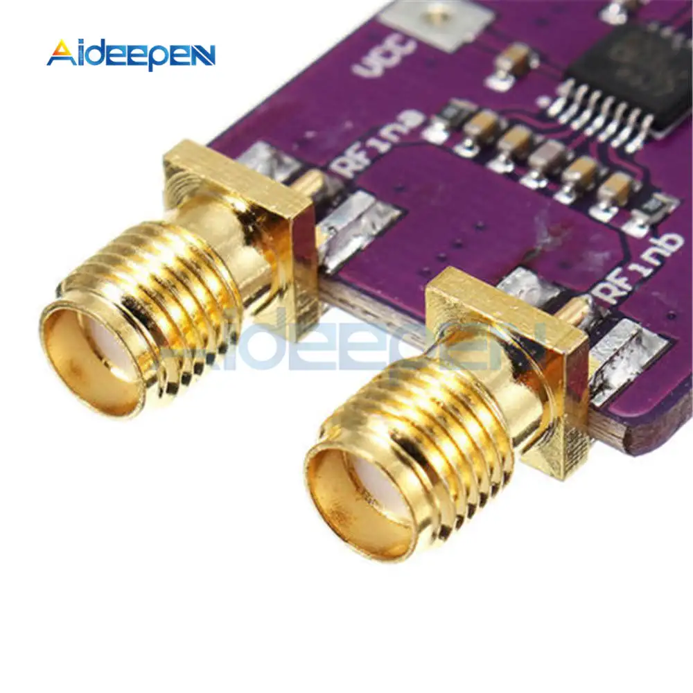
Module A, B input: access to the input signal to be measured, the input signal range of -60 ~ 0dBm (50Ω system).
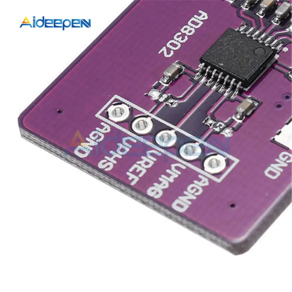
VMAG side: the amplitude ratio of two input signals, the formula is: VMAG = VSLP * log (VINA / VINB) + VCP, the exact amplitude of the scale factor of 30mV / dB, the center point of 900mV.
VPHS side: The phase ratio of the two input signals is calculated as follows: VPHS = VΦ [Φ (VINA) -Φ (VINB)] + VCP, the exact phase scale ratio is 10mV / degree and the center point is 900mV.
VREF: Enter the internally generated reference voltage, which is 1.8V
Connect the two signals to module A and B to measure the voltage of VMAG and VPHS. If VAMG voltage is greater than 900mV, the signal amplitude of input A is greater than that of input B, and VPHS is the same.
Package Include:
1PC x AD8302 Bandwidth Logarithmic Amplifier Board Amplitude Phase RF Detector Module Broadband Amplifier Module 2.7GHz for Arduino