


Description:
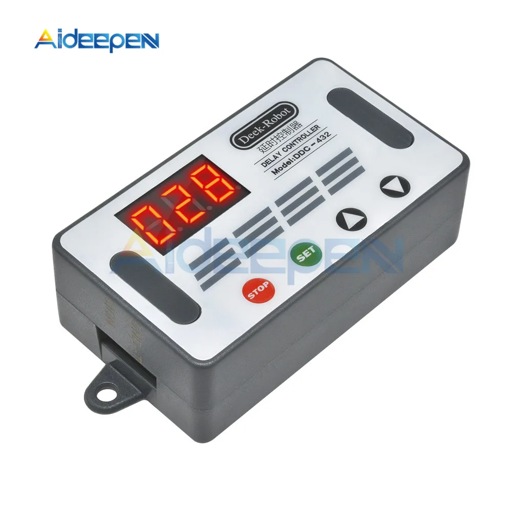
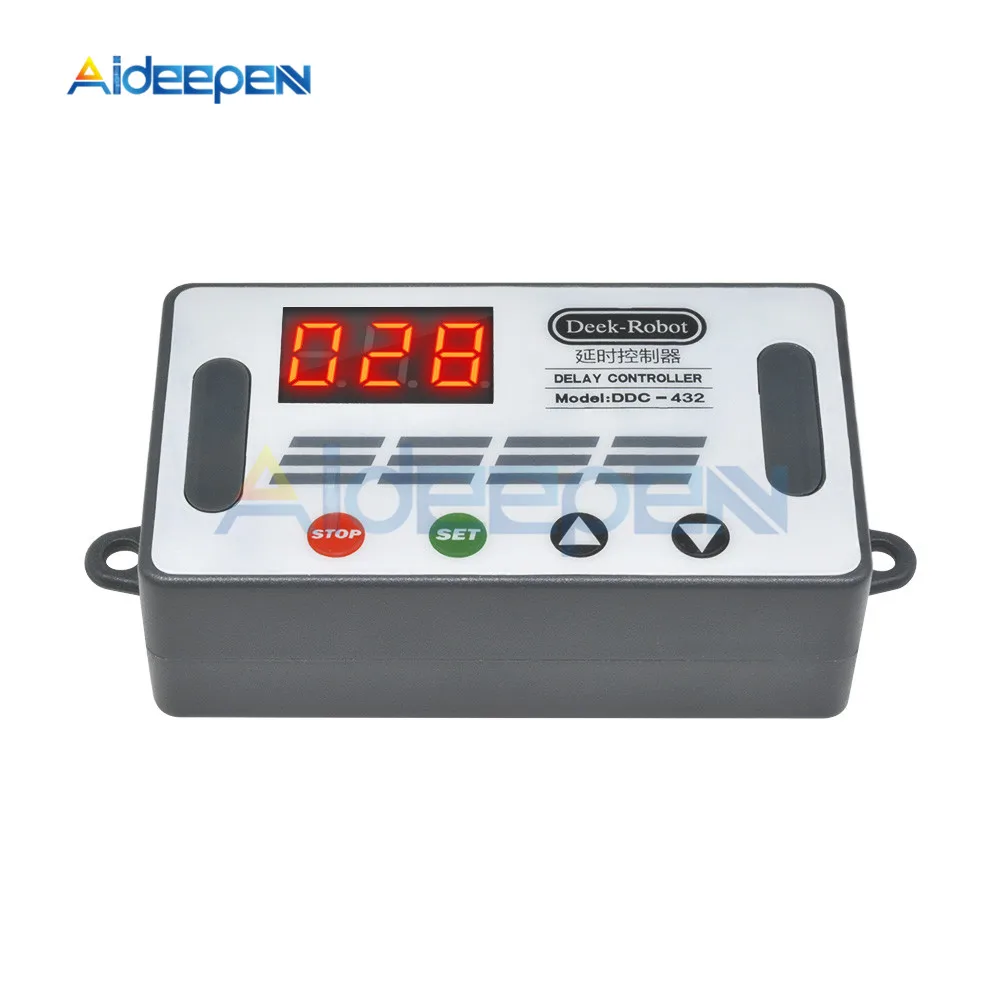
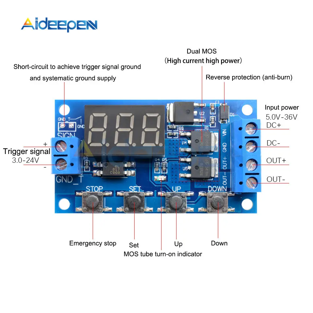
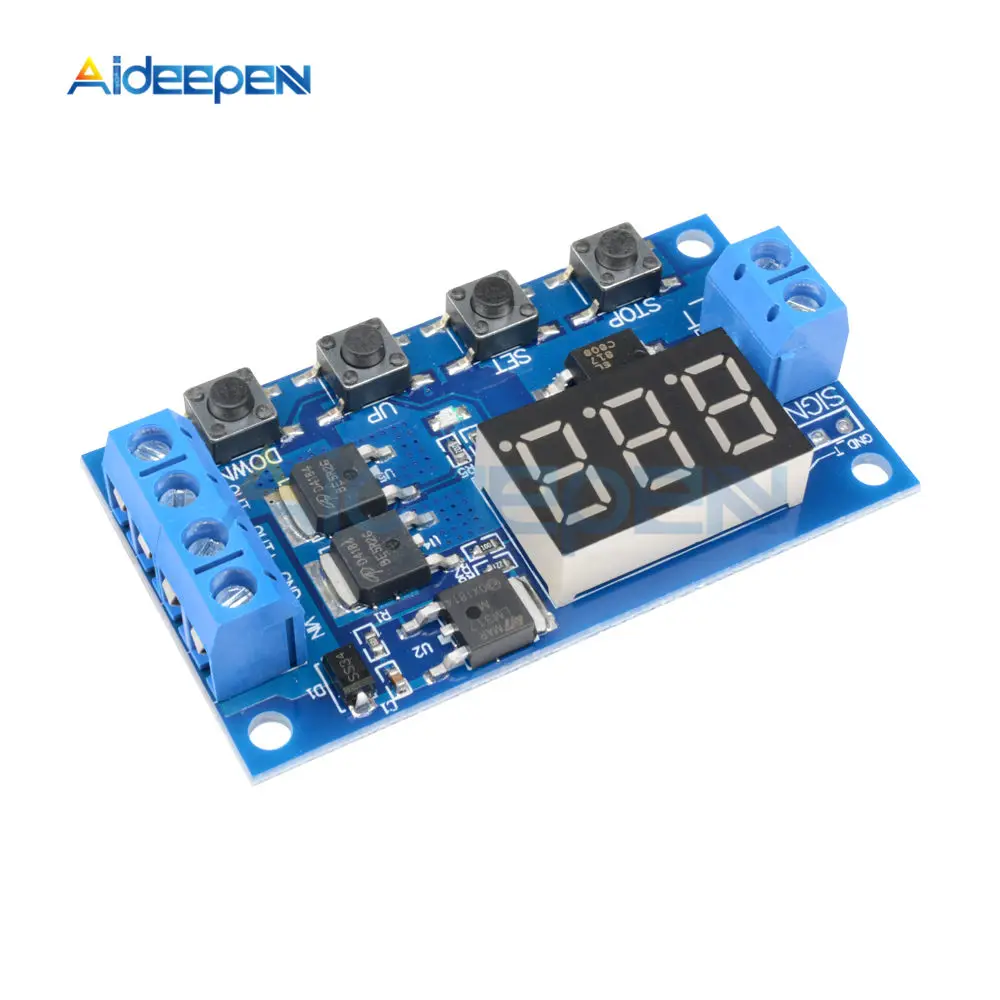
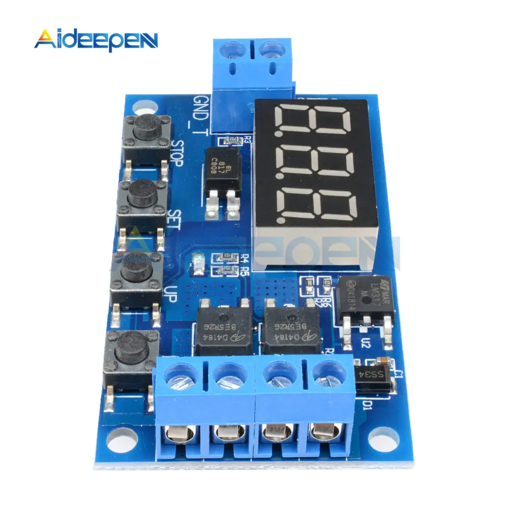
Dual MOS parallel active output, lower internal resistance, larger current, strong power interface, clear and simple, powerful, one-button emergency stop function (STOP button), with Reverse connection protection, reverse connection does not burn, power off memory. Increased sleep mode, after enabling, no operation within 5 minutes, automatically turn off the display, wake up any button! You can set different OP, CL, LOP parameters, these parameters are Independent of each other, save the settings parameters automatically power-down save and other functions, almost meet all needs!
Feature:
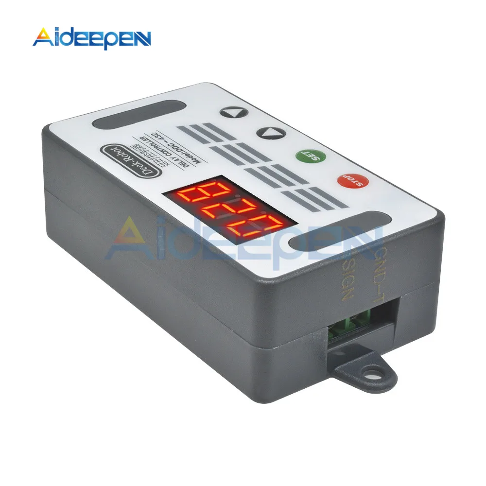
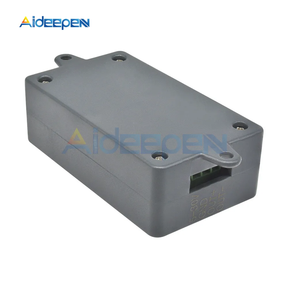
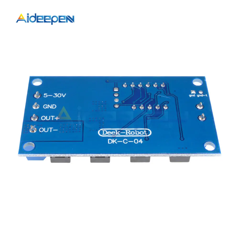
Working voltage: DC5V-DC30V (wide voltage anti-connection protection)
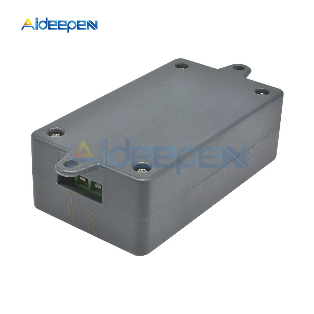
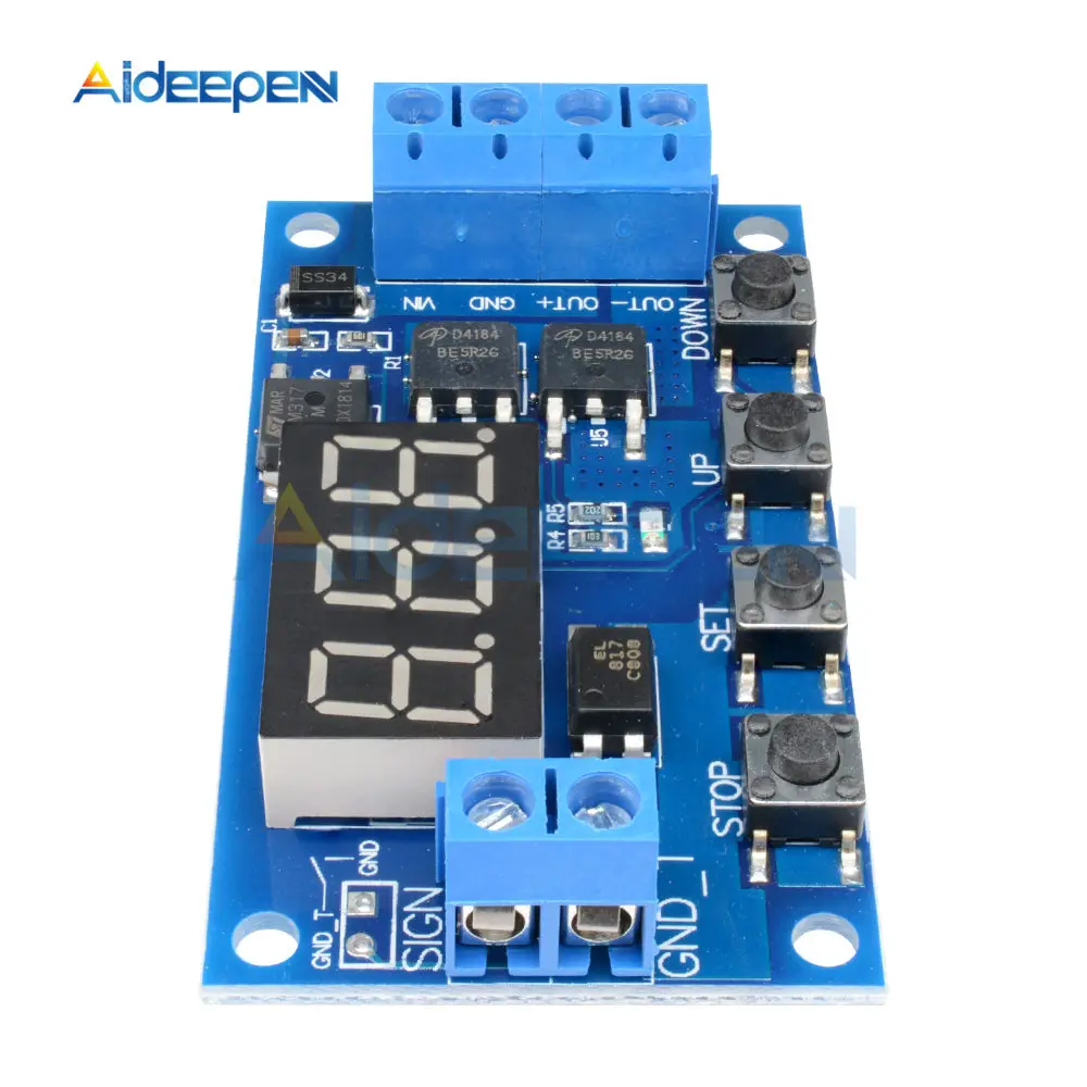
Trigger signal source: high-level trigger DC 3.0V—24V signal ground and system ground to improve the system's anti-interference ability can also short-circuit the ground
Output capacity: DC DC 5V--36V, continuous current 15A at normal temperature, power 400W!!! Under the condition of auxiliary heat dissipation, the maximum current can reach 30A
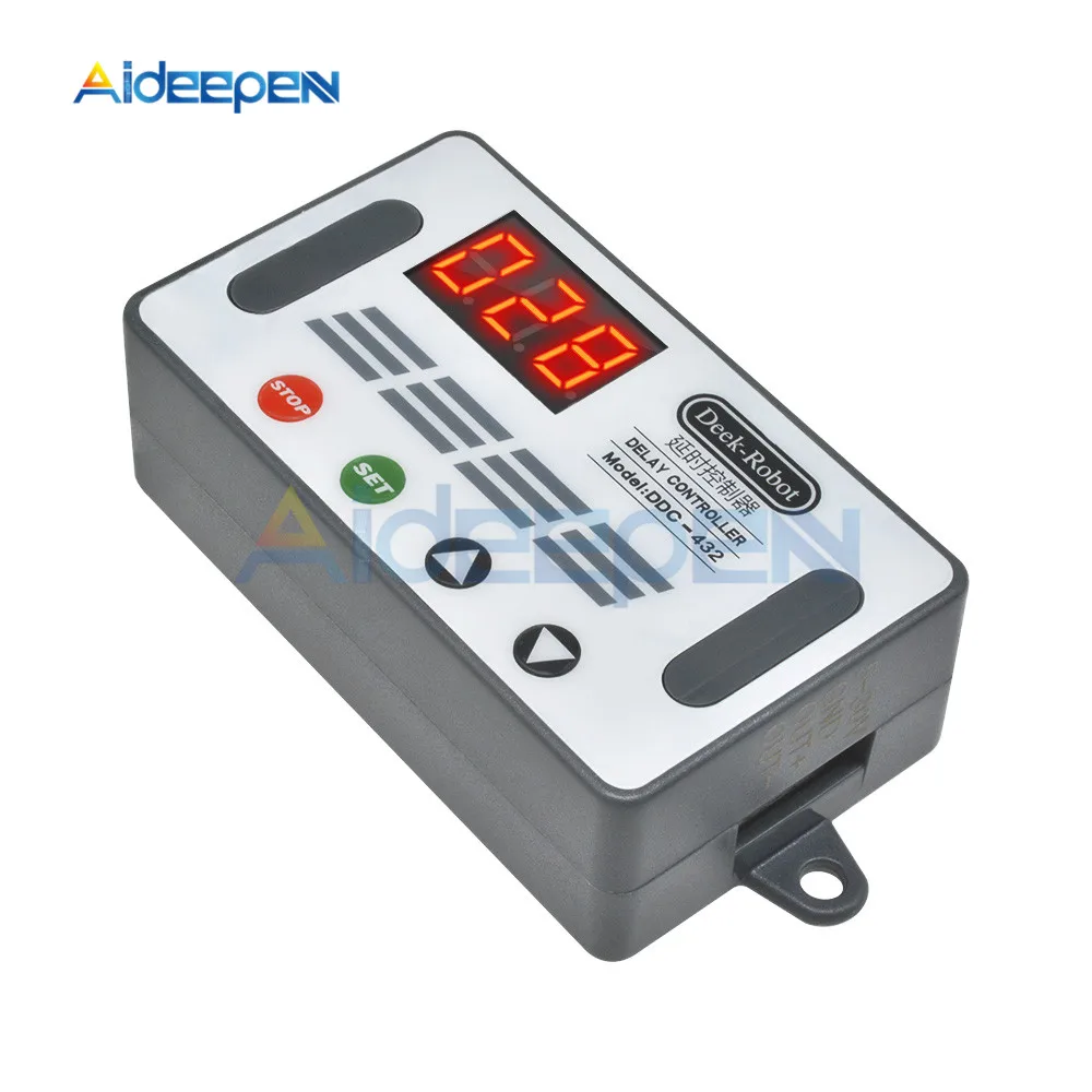
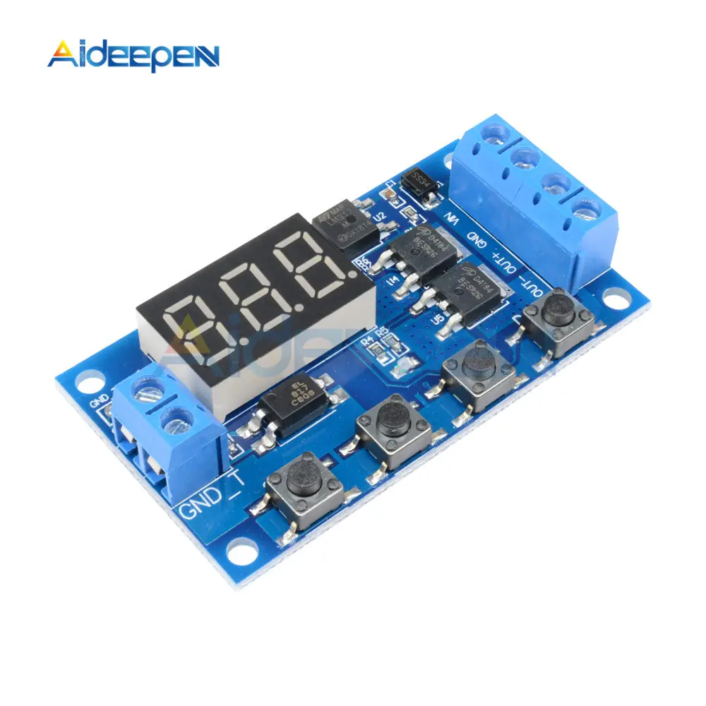
Product size: 64mm*35mm*19.3mm
Mounting hole: diameter 3mm
Working temperature: -40 ° C ~ 85 ° C
Operating Mode:
P1 mode: After the signal is triggered, the MOS transistor turns on the OP time and then turns off; in the OP time, the following operation
P1.1: The signal is triggered again.
P1.2: Signal triggers re-timed again
P1.3: The signal triggers reset again, the MOS tube is disconnected, and the timing is stopped.
P-2: Give the trigger signal, after the MOS transistor is disconnected from the CL time, the MOS transistor turns on the OP time. After the timing is completed, the MOS transistor is disconnected.
P3.1: Give the trigger signal, after the MOS transistor turns on the OP time, the MOS tube turns off the CL time, then loops the above action, the signal is given again in the loop, the MOS tube is disconnected, the timing is stopped; the number of cycles (LOP) can be set.
P3.2: No need to trigger signal after power-on, MOS tube turns on OP time, MOS tube disconnects CL time, loops the above action; loop number (LOP) can be set
P-4: Signal hold function If there is a trigger signal, the timing is cleared, the MOS transistor remains on; when the signal disappears, the MOS transistor is disconnected after timing the OP; during the timing, there is a signal and the timing is cleared.
Relay Enable Mode:
ON : MOS tube is allowed to conduct during OP conduction time
OFF : MOS tube is disabled, always off
Short press the STOP button on the main interface to switch between ON and OFF. The current state will flash, then return to the main interface. This function is the emergency stop function. One button is used to open and close the MOS tube.
Sleep mode (long press the stop button to view the current mode)
C-P sleep mode: within five minutes, without any operation, the digital tube automatically turns off the display, the program runs normally.
O-d normal mode: the digital tube is always on display
Press and hold the STOP button for 2 seconds and then release to switch the C-P and O-d states. The current state will flash and then return to the main interface.
Timing Range:
How to choose the timing range
After setting the parameter value in the mode selection interface, press the STOP button to select the timing range.
XXX. Decimal point is in one place, timing range: 1 second to 999 seconds
XX.X decimal point in ten, timing range: 0.1 seconds to 99.9 seconds
X.X.X. The decimal point is fully illuminated, the timing range is from 1 minute to 999 minutes.
For example, if you want to set the OP to 3.2 seconds, move the decimal point to ten digits, and the digital tube displays 03.2.
Parameter description: OP on time, CL off time, LOP cycle number 1-999 times, "---" stands for infinite loop
These parameters are independent of each other, but each mode shares these parameters. For example, when the on-time OP is set to 5 seconds in P1.1, the user wants to switch to the P1.2 mode, then when entering the P1.2 setting corresponding parameters, the OP also Will be 5 seconds
Displaying 000 on the main interface and pressing the SET button will display OPL, LOP and corresponding time XXX
If only OP in the mode, such as mode P1.1, P1.2, P1.3 time, then short press SET button will only display OP and corresponding time
If the mode has OP, CL, LOP such as mode P3.1, P3.2 short press SET button will display OP and corresponding time, CL and corresponding time, LOP and corresponding times
After setting the mode, it is very convenient to view the parameters set in the current mode by pressing the SET button on the main interface.
How to set parameters:
First determine the working mode of the MOS tube
According to the working mode of the MOS tube, in the main interface (when the module is powered on, it will flash the current working mode (default P1.1 mode), then enter the main interface "press and hold the SET button for 2 seconds and then release" to enter the mode. Select the interface, press the UP, DOWN button to select the mode to be set P1.1~P-4
After selecting the mode to be set (for example, P3.2), press the SET button to set the corresponding parameter. At this time, the parameter to be set will flash OP ON time, CL OFF time, LOP cycle number “---” means unlimited. The secondary cycle, through the UP, DOWN to adjust the parameter value, support long press (rapid increase or decrease) and short press (increase or decrease 1 unit); after setting the parameter value, select the decimal point position by short pressing the STOP button, select Timing range (corresponding time 0.1 seconds to 999 minutes); short press the SET button to set the next parameter of the current mode, the process is the same as above
After setting the parameters of the selected mode, press and hold the SET button for 2 seconds to release, the currently set mode will flash, then return to the main interface and set the parameters successfully.
Main interface: “000” (no decimal point) is displayed when the MOS tube is not working, and the MOS tube has a decimal point in the working state, which is clear.
Mode selection interface: long press SET button to enter, after setting is completed, long press SET button to exit, return to the main interface.
Package Included:
1 x DC 5V-30V Dual MOS Time Delay Relay High Level Trigger LED Digital Display Cycle Time Timer Delay Switch Circuit 12V 24V 0-999